Overview & Specs
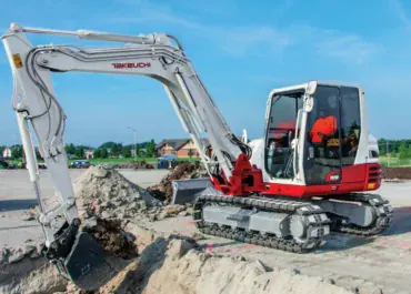
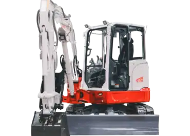
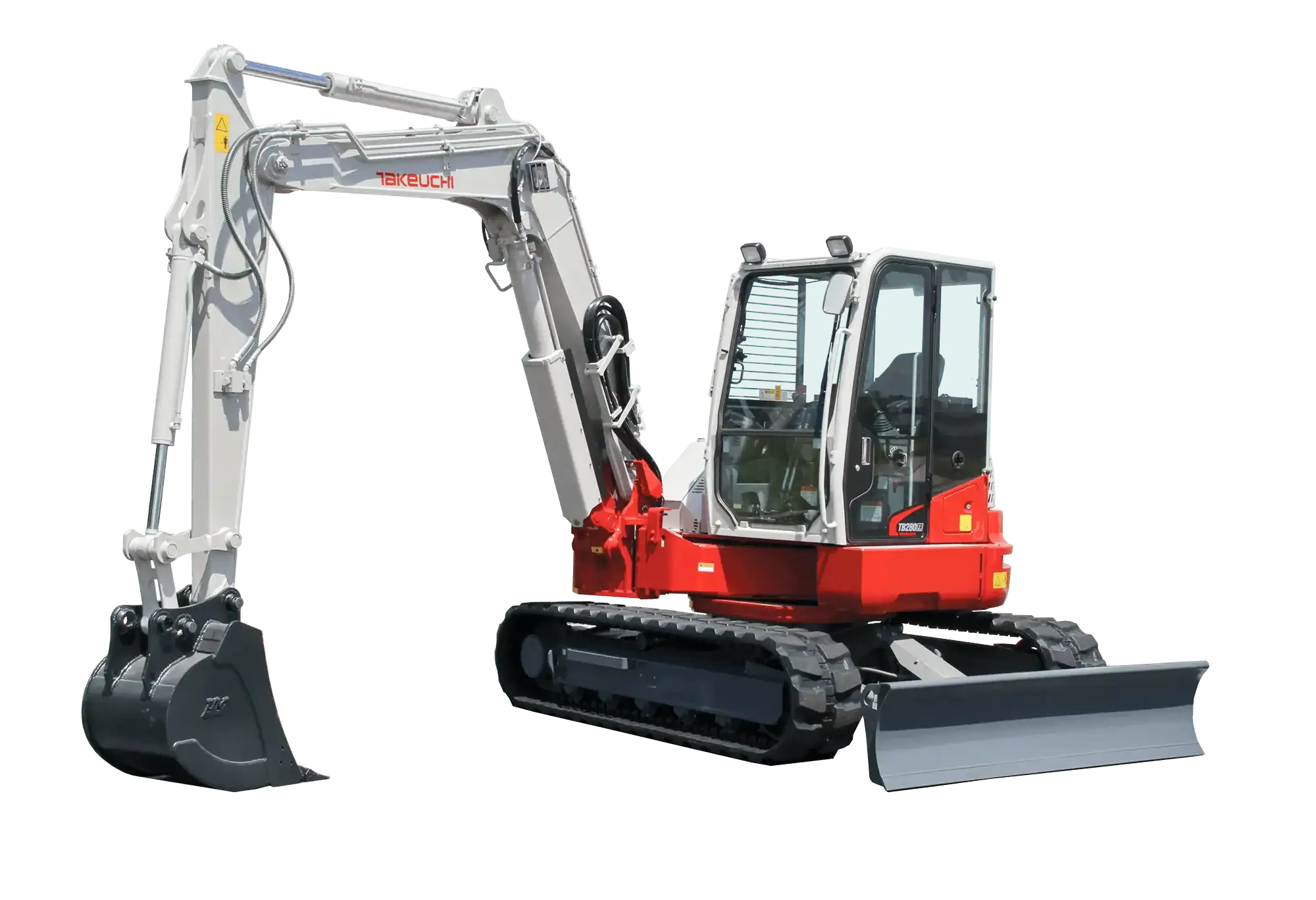
The Takeuchi TB280FR is a specialised choice for buyers whose main constraint is the relationship between the boom, the machine and the work area. Its side-to-side, or STS, boom arrangement is the reason to investigate it. It can offer a different way to position the tool and stow the front equipment, but that advantage should be demonstrated on a real recurring task before accepting the cost and logistics of an excavator in this weight class.
For Canadian farmyards, property contractors and constrained construction sites, the useful question is whether the layout removes a positioning problem that an ordinary boom arrangement leaves unresolved. A distinctive design is valuable when it changes the work. It is less persuasive when the site is open and the same job can be completed conveniently with a simpler shortlist.
On This Page
ToggleWhat STS and full rotation actually describe
Takeuchi’s North American product page describes rotation nearly within the track width when the boom is fully stowed upright. That condition matters. It is not a promise that every bucket position, attachment or working movement remains within the tracks.
The April 2019 brochure describes the STS arrangement and its offset visibility benefit. Treat those as layout features to test. The operator still needs a suitable working envelope for the complete machine, front equipment, hoses and any material being handled.
A helpful demonstration has two parts. First establish the permitted stowed movement with the actual equipment. Then demonstrate the useful digging or placement cycle. Passing the first test does not automatically pass the second, because extending the front equipment changes the space occupied.
Reference specifications for the documented package
| Measurement | April 2019 brochure | Decision it informs |
|---|---|---|
| Operating mass, cab with rubber / steel tracks | 8,530 / 8,730 kg | Track configuration and transport |
| Engine output | 69.2 hp at 2,000 rpm | Engine reference, not a lift rating |
| Undercarriage width / tail radius | 2,300 / 1,280 mm | Access and rear envelope |
| Maximum depth / ground-level reach | 4,540 / 7,045 mm | Working-range assessment |
| Primary auxiliary flow | 148 L/min | Initial circuit-specific tool screening |
The source identifies a serial reference for the described package. Its force figures differ from some web summaries, so this guide does not rank the machine using a disputed breakout number. The metric references are explicitly tied to the dated brochure; the offered machine still requires its own configuration check.
Start with the position you cannot currently achieve
The most convincing reason to buy an STS machine is a recurring task where another layout forces repeated moves, an awkward view or an unproductive digging position. Write down that constraint precisely. “Tight site” is too broad: the problem might be entry width, rear clearance, front geometry or material storage, and each needs a different solution.
Sketch the excavation and appropriate machine positions, then add obstructions and the material destination. Identify the movement that causes trouble. Is it approaching the cut, keeping a useful view of the tool, extracting material or swinging toward the receiving location? The TB280FR should be evaluated at that point in the sequence.
Do not assume the same track position can be retained for an entire project simply because the boom moves laterally. The useful envelope changes with the task and attachment. Where the machine must reposition anyway for reach or ground conditions, the layout advantage may be smaller than a sales demonstration suggests.
The tail-swing guide provides background, but this model deserves an assessment of its front arrangement as well as its rear. A compact counterweight and an offset boom answer related but different site questions.
Visibility should be tested from the operator’s seat
Visibility claims become useful when tied to what the operator must actually see. During an appropriate demonstration, assess the bucket edge, intended cut and material placement from the normal seating position. Include the attachment proposed for regular use rather than a convenient demonstration bucket.
An offset view may help one part of the task while another movement introduces a different obstruction. Record the whole sequence. The objective is not to prove that one position looks good; it is to determine whether the operator can perform the recurring job with a practical view and controlled movement.
For a shared machine, include the people who will normally operate it. Seat adjustment, control reach and familiarity affect how they use the layout. A brief explanation followed by a few unloaded movements is a weak basis for predicting a full shift’s work.
Keep visibility separate from exclusion zones and operating procedures. Being able to see a location does not establish permission to work there or eliminate the need for the site’s normal controls. This is an equipment-selection assessment, not a substitute for the operating manual or site plan.
Eight-tonne-class capability brings real logistics
The machine’s specialised rotation arrangement does not make its transport footprint equivalent to that of a much smaller excavator. The brochure’s rubber-track mass reference is 8,530 kg before resolving the exact offered equipment and separately carried tools. Access width and supporting arrangements need to fit the actual package.
Survey the complete route, including turns, overhead restrictions and the position where attachments will be unloaded. A machine may rotate compactly after arrival but still be difficult to deliver to the required location. Include access preparation and restoration in the project comparison.
For a farm with occasional large projects, contracted delivery can be compared with owning dedicated transport equipment. For a contractor moving frequently, loading, securement, travel and scheduling become regular operating costs. A useful site feature should not be assessed independently of those demands.
Use actual weights, ratings and applicable requirements for the complete hauling combination. Do not infer suitability from a trailer’s length or from the word compact in an equipment category. The machine, tools and transport arrangement must be assessed together.
Working range: separate reach from useful excavation
The maximum depth and ground-level reach describe different positions in the brochure drawing. Neither establishes that a bucket can fill, extract and discharge effectively at every point inside an imagined rectangle. The task needs an appropriate path through the actual envelope.
With the TB280FR, evaluate that path in the relevant boom arrangement. A general maximum figure should not be treated as proof of equal capability in every offset position. Obtain the applicable configuration information and demonstrate the important task rather than extrapolating from one illustration.
The Aglist range guide helps establish the required measurements. Record standing elevation, horizontal positions, excavation shape and material destination. The site plan determines suitable machine positions; the excavator is then assessed for reaching from them.
Loading deserves its own check. Clearing a container edge is not the same as placing material across its useful area. Include the receiving equipment in the comparison and observe whether its position creates unnecessary waiting or movement.
Hydraulic tools must fit the whole arrangement
The primary auxiliary flow reference makes this a candidate for a range of powered-tool assessments, but flow alone is not approval. Identify the tool’s pressure, accepted flow, return requirements, controls, mass and mounting. Confirm the complete installation for the exact machine.
The offset boom also makes hose routing and movement clearance important acceptance questions. A tool that connects and operates in one position still needs an appropriate installation through the permitted working and stowed movements. Have that checked as part of commissioning rather than improvising a solution after delivery.
Where a thumb and coupler are involved, document their interaction with each bucket. The coupler guide explains why the connection is more than a convenience feature. Added components can affect geometry and mass as well as tool-changing time.
Do not use the machine’s size or hydraulic capacity as a lifting rating. Apply the correct load chart and its conditions for the actual configuration, radius, direction and height. A successful gripping demonstration does not independently establish a permitted lift.
When the special layout can justify its cost
Measure the delay the design is expected to remove. Suppose a hypothetical constrained job involves twelve avoidable repositioning events of four minutes each. Eliminating them would save 48 minutes. If only half can actually be removed because reach and material placement still require moves, the saving becomes 24 minutes.
At 40 such jobs annually, those assumptions produce 16 hours of saved time. At an assumed internal value of C$110 per hour, that is C$1,760 before additional ownership, maintenance and transport costs. These are planning examples, not measured TB280FR output or Canadian market rates.
The calculation can support a decision only if the saved time has practical value and the finished result is equivalent. A feature may also improve the feasibility of a particular job, but that benefit needs a documented job pipeline rather than an unsupported revenue forecast.
If most work takes place in open areas, compare a conventional machine on equal terms. The specialised arrangement may still suit the operator and tooling, but the original tight-site argument should not be applied to jobs where that constraint does not exist.
Seasonal use and service planning
The documented package includes a cab with climate equipment and an engine with DOC and DPF after-treatment. Inspect the actual functions and use the applicable operating and service information. A used listing should not be assumed to represent an unchanged factory package.
For Canadian shoulder-season work, consider visibility, warm-up requirements and the materials encountered. Frozen ground and poor access conditions can alter the task independently of the operator’s comfort. Do not turn the presence of a heated cab into a promise of identical year-round production.
The brochure describes a tilting cab for service access. Treat that as a service provision to be used according to the proper procedure, not an invitation to improvise inspection access. Establish how maintenance will be performed at the working location and whether appropriate support is available.
Parts access and technician availability should be based on real local arrangements. No guaranteed Canadian stock level, service life or repair cost follows from the manufacturer’s feature list. Ask for concrete support information when downtime would interrupt essential work.
Inspecting a used STS machine
Verify the serial identity, tracks, boom arrangement, arm, blade, coupler and auxiliary installation before assessing condition. Record modifications and obtain their documentation. A package with several unfamiliar attachments should not be valued as complete until compatibility is established.
A qualified inspector should assess the boom’s pivots and linkage, structure, cylinders, hoses and movement, alongside the ordinary undercarriage, hydraulic and engine checks. Those are inspection priorities arising from the mechanism, not claims that the TB280FR has a known failure frequency.
Observe representative operation after the appropriate checks. Include the offset and stowed movements relevant to the intended work, with the actual approved tool package. Investigate unexplained movement, interference or warnings rather than assuming they are normal characteristics of an unusual design.
Separate purchase price, required repairs and missing equipment from optional upgrades. A specialist layout is worthwhile only when the particular machine is serviceable and suited to the work. An attractive feature cannot compensate for unresolved condition or transport problems.
Frequently asked questions
Can it rotate within the tracks while digging?
The manufacturer’s compact-rotation description is conditional on the boom being fully stowed upright and says nearly within the track width. Do not extend that statement to every working position or attachment.
Is STS the same as ordinary boom swing?
The TB280FR uses its own side-to-side boom arrangement. Evaluate its documented movement and practical effect rather than assuming that another excavator’s offset figures describe the same layout.
Would a smaller machine be a better property choice?
Possibly. If the tasks fit a smaller carrier and access or transport is the main constraint, compare options such as the TB240 or TB250-2 on the actual job. They are alternatives to investigate, not equivalents in every capability.
Does the hydraulic flow establish a universal attachment class?
No. It is one reference for a specific circuit. The complete tool and installation requirements determine suitability.
What should make this model the preferred choice?
A demonstrated improvement in a recurring positioning problem, together with verified range, attachment compatibility, condition and practical delivery. The STS layout should solve a defined constraint that matters often enough to justify the complete package.
Share your experience
Help other Canadian buyers — leave a quick review for the
Takeuchi TB280FR
There are no reviews yet. Be the first one to write one.